Guide for Powering On VG710
Power Supply
Power input range | Recommended power | Ways to obtain power |
9-36 V DC | 18 W | (1) Vehicle battery (2) Storage battery (3) Lighter (4) Power adapter (used indoors) |
Power Interface
PIN | Definition | Color | PIN | Definition | Color |
1 | NC | 2 | IGT | White | |
3 | GND | Black | 4 | V+ | Red |
In a normal engineering environment
Connect to the power supply V+, GND, and ignition sense cable. Connect the ignition sense signal cable to the ignition sense cable, as shown below.

In a test environment(Indoor test in office)
Accessories
- Power Adapter

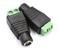
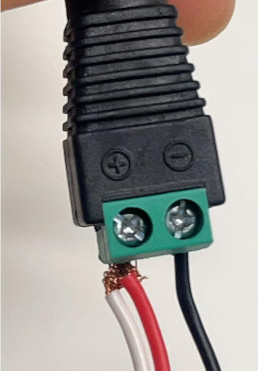
- DC 5.5*2.1mm Female Connector
- 4-pins Power cable

How to connect
- Connect the Power Adapter with DC Connector.

- Connect the ignition sense cable and the anode in parallel in DC Connector's Positive pin, and connect the GND in DC Connector's Negative pin.

- Combine the Power Adpater+DC Connector+4-pins Power cable. Then Plug the 4-pins Power cable's 4-pin side into VG710's power input interface, plug in the Power Adapetr.

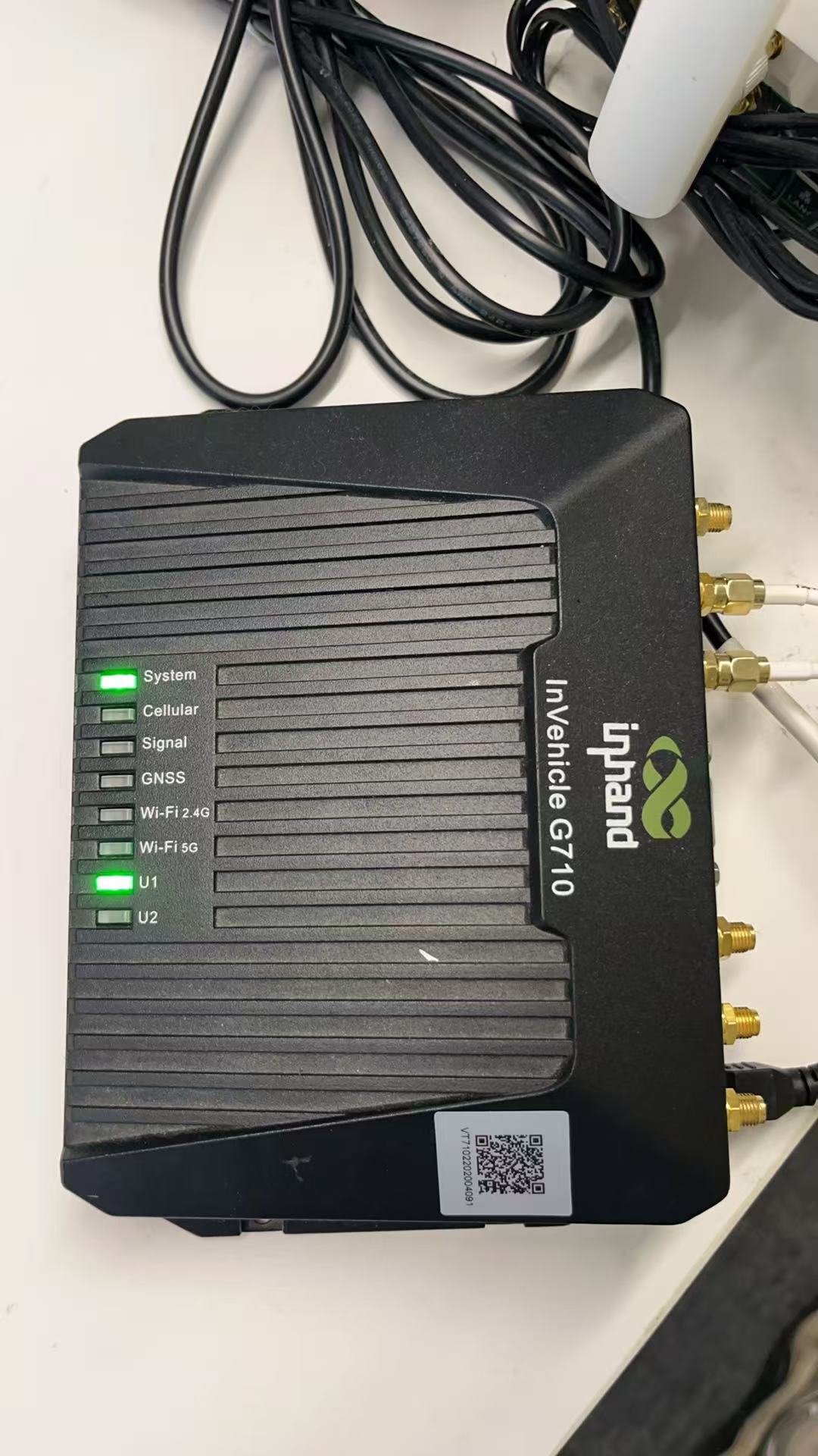
- Check the LED Status of VG710, which shows powed on successfully.
Note
The device cannot be started if the ignition sense cable is not connected.
Topic Participants
Irene Peng